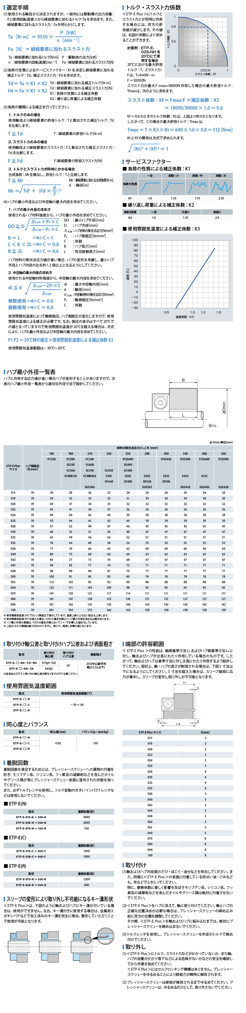
LYZON_test Detailed Product Samples] ETP-E Plus Model
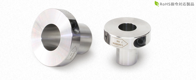
The shaft and hub can be easily and quickly connected with a single bolt. Moreover, the concentricity is excellent at 0.02 mm, making it ideal for applications that require high precision and frequent connection/disconnection. Since it is designed to be tightened from the radial direction, it does not take up much work space.
ETP-E Plus Model Specifications
ETP-E Plus (N) Type
Specifications
| type | Axial Tolerance | Allowable torque [N-m] |
Allowable Thrust Force [N] |
Allowable Radial Load [N] |
Shaft side pressure [N/mm2] |
Hub side
pressure [N/mm2] |
Tightening torque [N-m] |
Moment of
inertia [kg・m2] |
Mass [kg] | Price [yen] | Purchase | |
|---|---|---|---|---|---|---|---|---|---|---|---|---|
| h7 | k6(j6) | |||||||||||
| ETP-E-015-N | ● | 46 | 5100 | 500 | 90 | 70 | 7 | 0.042 × 10⁻³ | 0.16 | 14,400 |
|
|
| ETP-E-019-N | ● | ○ | 85 | 7300 | 1000 | 90 | 70 | 7 | 0.063 × 10⁻³ | 0.20 | 14,670 |
|
| ETP-E-020-N | ● | 110 | 9100 | 1000 | 90 | 70 | 7 | 0.069 × 10⁻³ | 0.21 | 14,810 |
|
|
| ETP-E-022-N | ● | ○ | 130 | 9600 | 1200 | 90 | 70 | 7 | 0.095 × 10⁻³ | 0.25 | 15,310 |
|
| ETP-E-024-N | ● | ○ | 190 | 13000 | 1400 | 90 | 70 | 7 | 0.109 × 10⁻³ | 0.26 | 15,800 |
|
| ETP-E-025-N | ● | 230 | 15000 | 1500 | 90 | 70 | 7 | 0.114 × 10⁻³ | 0.27 | 16,570 |
|
|
| ETP-E-028-N | ● | ○ | 280 | 16000 | 1800 | 90 | 70 | 7 | 0.166 × 10⁻³ | 0.33 | 16,740 |
|
| ETP-E-030-N | ● | 380 | 21000 | 2000 | 90 | 70 | 7 | 0.185 × 10⁻³ | 0.35 | 16,920 |
|
|
| ETP-E-032-N | ● | ○ | 440 | 22000 | 2200 | 90 | 70 | 7 | 0.244 × 10⁻³ | 0.41 | 18,010 |
|
| ETP-E-035-N | ● | ○ | 640 | 30000 | 2500 | 90 | 70 | 7 | 0.317 × 10⁻³ | 0.47 | 19,090 |
|
| ETP-E-038-N | ● | ○ | 890 | 38000 | 2800 | 90 | 70 | 24 | 0.756 × 10⁻³ | 0.83 | 20,560 |
|
| ETP-E-040-N | ● | 1100 | 45000 | 3000 | 90 | 70 | 24 | 0.836 × 10⁻³ | 0.88 | 22,020 |
|
|
| ETP-E-042-N | ● | ○ | 1100 | 43000 | 3200 | 90 | 70 | 24 | 0.959 × 10⁻³ | 0.95 | 22,530 |
|
| ETP-E-045-N | ● | 1400 | 51000 | 3500 | 90 | 70 | 24 | 1.152 × 10⁻³ | 1.03 | 23,030 |
|
|
| ETP-E-048-N | ● | ○ | 1700 | 57000 | 4000 | 90 | 70 | 24 | 1.430 × 10⁻³ | 1.09 | 23,550 |
|
| ETP-E-050-N | ● | 1900 | 63000 | 4500 | 90 | 70 | 24 | 1.497 × 10⁻³ | 1.18 | 24,050 |
|
|
| ETP-E-055-N | ● | ○ | 2400 | 71000 | 5000 | 90 | 70 | 24 | 2.130 × 10⁻³ | 1.46 | 31,230 |
|
| ETP-E-060-N | ● | 3300 | 90000 | 5300 | 90 | 70 | 24 | 3.089 × 10⁻³ | 1.79 | 33,030 |
|
|
| ETP-E-070-N | ● | 5600 | 130000 | 6400 | 90 | 70 | 40 | 6.951×10⁻³ | 2.93 | 75,900 | Made to order | |
| ETP-E-080-N | ● | 8700 | 180000 | 7500 | 90 | 70 | 40 | 10.02×10⁻³ | 3.58 | 82,310 | Made to order | |
| ETP-E-090-N | ● | 12000 | 230000 | 8600 | 90 | 70 | 40 | 14.84×10⁻³ | 4.54 | 89,250 | Made to order | |
| ETP-E-100-N | ● | 17000 | 280000 | 9700 | 90 | 70 | 40 | 21.00×10⁻³ | 5.51 | 99,590 | Made to order | |
- Sizes marked with ○ are standard specifications, corresponding to shaft tolerance h7 (g6, h6), and sizes marked with ○ can correspond to shaft tolerance k6 (j6) as an option.
- ETP-E-035-NK (k6 (j6) tolerance compatible) can also accommodate mating axis tolerances of 0 to +0.010.
- Allowable torque is the value when thrust force is zero, and allowable thrust force is the value when torque is zero.
- Allowable torque, allowable thrust force, shaft side pressure, and hub side pressure are values at 20°C.
- ETP-E-070, 080, 090 and 100 are made-to-order products.
Dimensions
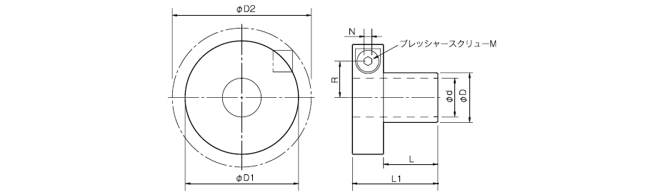
| type | d | D | D1 | D2 | L | L1 | R | N | M |
|---|---|---|---|---|---|---|---|---|---|
| ETP-E-015-N | 15 | 18 | 46 | 50 | 23 | 37 | 15.1 | 5 | 1-M10 |
| ETP-E-019-N | 19 | 23 | 50.5 | 55 | 25 | 39 | 17.4 | 5 | 1-M10 |
| ETP-E-020-N | 20 | 24 | 51.5 | 56 | 27 | 41 | 18 | 5 | 1-M10 |
| ETP-E-022-N | 22 | 27 | 55.5 | 61 | 29 | 43 | 19.3 | 5 | 1-M10 |
| ETP-E-024-N | 24 | 29 | 57.5 | 63 | 30 | 44 | 20.3 | 5 | 1-M10 |
| ETP-E-025-N | 25 | 30 | 58 | 63 | 32 | 46 | 20.8 | 5 | 1-M10 |
| ETP-E-028-N | 28 | 34 | 63 | 70 | 34 | 48 | 22.6 | 5 | 1-M10 |
| ETP-E-030-N | 30 | 36 | 64.5 | 71 | 36 | 50 | 23.6 | 5 | 1-M10 |
| ETP-E-032-N | 32 | 39 | 68.5 | 78 | 38 | 52 | 24.8 | 5 | 1-M10 |
| ETP-E-035-N | 35 | 42 | 73 | 86 | 41 | 55 | 26.4 | 5 | 1-M10 |
| ETP-E-038-N | 38 | 46 | 84.5 | 92.5 | 47 | 67 | 31 | 8 | 1-M16 |
| ETP-E-040-N | 40 | 48 | 86.5 | 94 | 50 | 70 | 32 | 8 | 1-M16 |
| ETP-E-042-N | 42 | 51 | 89 | 96.5 | 50 | 70 | 33.2 | 8 | 1-M16 |
| ETP-E-045-N | 45 | 54 | 93 | 101 | 52 | 72 | 34.8 | 8 | 1-M16 |
| ETP-E-048-N | 48 | 59 | 97 | 104 | 53 | 73 | 36.8 | 8 | 1-M16 |
| ETP-E-050-N | 50 | 60 | 98.5 | 106 | 54 | 74 | 37.5 | 8 | 1-M16 |
| ETP-E-055-N | 55 | 67 | 106 | 116 | 59 | 79 | 40.5 | 8 | 1-M16 |
| ETP-E-060-N | 60 | 73 | 115.5 | 123.5 | 63 | 83 | 43.3 | 8 | 1-M16 |
| ETP-E-070-N | 70 | 85 | 135.5 | 150 | 77 | 101 | 50.8 | 10 | 1-M20 |
| ETP-E-080-N | 80 | 97 | 145.5 | 160 | 86 | 110 | 56.3 | 10 | 1-M20 |
| ETP-E-090-N | 90 | 109 | 155.5 | 169 | 95 | 119 | 61.8 | 10 | 1-M20 |
| ETP-E-100-N | 100 | 121 | 166 | 180 | 104 | 128 | 67.3 | 10 | 1-M20 |
- ΦD2 dimensions are before tightening <ETP-E Plus>.
- The nominal size of pressure screw M is quantity - nominal size of screw.
ETP-E Plus (C) type (simple anti-rust specification) *Made to order
Specifications
| Type | axial tolerance | Allowable torque [N-m] |
Allowable Thrust Force [N] |
Allowable Radial Load [N] |
Shaft side pressure [N/mm2] |
Hub side pressure [N/mm2] |
Tightening torque [N-m] |
Moment of inertia [kg・m2] |
Mass [kg] | Price [yen] | Purchase | .|
|---|---|---|---|---|---|---|---|---|---|---|---|---|
| h7 | k6(j6) | |||||||||||
| ETP-E-015-C | ● | 34 | 3800 | 500 | 90 | 70 | 7 | 0.042 × 10⁻³ | 0.16 | 17,330 |
|
|
| ETP-E-019-C | ● | ○ | 63 | 5400 | 1000 | 90 | 70 | 7 | 0.063 × 10⁻³ | 0.20 | 17,610 |
|
| ETP-E-020-C | ● | 82 | 6800 | 1000 | 90 | 70 | 7 | 0.069 × 10⁻³ | 0.21 | 17,820 |
|
|
| ETP-E-022-C | ● | ○ | 97 | 7200 | 1200 | 90 | 70 | 7 | 0.095 × 10⁻³ | 0.25 | 18,430 |
|
| ETP-E-024-C | ● | ○ | 142 | 9700 | 1400 | 90 | 70 | 7 | 0.109 × 10⁻³ | 0.26 | 19,010 |
|
| ETP-E-025-C | ● | 172 | 11200 | 1500 | 90 | 70 | 7 | 0.114 × 10⁻³ | 0.27 | 19,920 |
|
|
| ETP-E-028-C | ● | ○ | 210 | 12000 | 1800 | 90 | 70 | 7 | 0.166 × 10⁻³ | 0.33 | 20,130 |
|
| ETP-E-030-C | ● | 285 | 15000 | 2000 | 90 | 70 | 7 | 0.185 × 10⁻³ | 0.35 | 20,340 |
|
|
| ETP-E-032-C | ● | ○ | 330 | 16000 | 2200 | 90 | 70 | 7 | 0.244 × 10⁻³ | 0.41 | 21,640 |
|
| ETP-E-035-C | ● | ○ | 480 | 22000 | 2500 | 90 | 70 | 7 | 0.317 × 10⁻³ | 0.47 | 22,910 |
|
| ETP-E-038-C | ● | ○ | 667 | 28000 | 2800 | 90 | 70 | 24 | 0.756 × 10⁻³ | 0.83 | 24,670 |
|
| ETP-E-040-C | ● | 825 | 33000 | 3000 | 90 | 70 | 24 | 0.836 × 10⁻³ | 0.88 | 26,410 |
|
|
| ETP-E-042-C | ● | ○ | 825 | 32000 | 3200 | 90 | 70 | 24 | 0.959 × 10⁻³ | 0.95 | 27,030 |
|
| ETP-E-045-C | ● | 1050 | 38000 | 3500 | 90 | 70 | 24 | 1.152 × 10⁻³ | 1.03 | 27,650 |
|
|
| ETP-E-048-C | ● | ○ | 1275 | 42000 | 4000 | 90 | 70 | 24 | 1.430 × 10⁻³ | 1.09 | 28,260 |
|
| ETP-E-050-C | ● | 1425 | 47000 | 4500 | 90 | 70 | 24 | 1.497 × 10⁻³ | 1.18 | 28,880 |
|
|
| ETP-E-055-C | ● | ○ | 1800 | 53000 | 5000 | 90 | 70 | 24 | 2.130 × 10⁻³ | 1.46 | 37,610 |
|
| ETP-E-060-C | ● | 2475 | 67000 | 5300 | 90 | 70 | 24 | 3.089 × 10⁻³ | 1.79 | 39,790 |
|
|
- Sizes marked with ○ are standard specifications, corresponding to shaft tolerance h7 (g6, h6), and sizes marked with ○ can correspond to shaft tolerance k6 (j6) as an option.
- ETP-E-035-CK (k6 (j6) tolerance compatible) can also accommodate mating axis tolerances of 0 to +0.010.
- Allowable torque is the value when thrust force is zero, and allowable thrust force is the value when torque is zero.
- Allowable torque, allowable thrust force, shaft side pressure, and hub side pressure are values at 20°C.
Dimensions
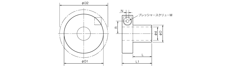
Unit [mm]
| type expression | d | D | D1 | D2 | L | L1 | R | N | M |
|---|---|---|---|---|---|---|---|---|---|
| ETP-E-015-C | 15 | 18 | 46 | 49 | 23 | 37 | 15.1 | 5 | 1-M10 |
| ETP-E-019-C | 19 | 23 | 50.5 | 53 | 25 | 39 | 17.4 | 5 | 1-M10 |
| ETP-E-020-C | 20 | 24 | 51.5 | 55 | 27 | 41 | 18 | 5 | 1-M10 |
| ETP-E-022-C | 22 | 27 | 55.5 | 61 | 29 | 43 | 19.3 | 5 | 1-M10 |
| ETP-E-024-C | 24 | 29 | 57.5 | 63 | 30 | 44 | 20.3 | 5 | 1-M10 |
| ETP-E-025-C | 25 | 30 | 58 | 63 | 32 | 46 | 20.8 | 5 | 1-M10 |
| ETP-E-028-C | 28 | 34 | 63 | 70 | 34 | 48 | 22.6 | 5 | 1-M10 |
| ETP-E-030-C | 30 | 36 | 64.5 | 71 | 36 | 50 | 23.6 | 5 | 1-M10 |
| ETP-E-032-C | 32 | 39 | 68.5 | 78 | 38 | 52 | 24.8 | 5 | 1-M10 |
| ETP-E-035-C | 35 | 42 | 73 | 86 | 41 | 55 | 26.4 | 5 | 1-M10 |
| ETP-E-038-C | 38 | 46 | 84.5 | 90 | 47 | 67 | 31 | 8 | 1-M16 |
| ETP-E-040-C | 40 | 48 | 86.5 | 92 | 50 | 70 | 32 | 8 | 1-M16 |
| ETP-E-042-C | 42 | 51 | 89 | 94 | 50 | 70 | 33.2 | 8 | 1-M16 |
| ETP-E-045-C | 45 | 54 | 93 | 101 | 52 | 72 | 34.8 | 8 | 1-M16 |
| ETP-E-048-C | 48 | 59 | 97 | 104 | 53 | 73 | 36.8 | 8 | 1-M16 |
| ETP-E-050-C | 50 | 60 | 98.5 | 106 | 54 | 74 | 37.5 | 8 | 1-M16 |
| ETP-E-055-C | 55 | 67 | 106 | 116 | 59 | 79 | 40.5 | 8 | 1-M16 |
| ETP-E-060-C | 60 | 73 | 115.5 | 133 | 63 | 83 | 43.3 | 8 | 1-M16 |
- ΦD dimensions are before tightening <ETP-E Plus>.
- The nominal size of pressure screw M is quantity - nominal size of screw.
ETP-E Plus (R) (Stainless steel specification)
Specifications
| Type | axial tolerance | Allowable torque [N-m] | Allowable Thrust Force [N] | Allowable radial load [N] | Axial side pressure [N/mm2] | Hub side pressure [N/mm2] | Tightening torque [N/m] | Moment of inertia [kg・m2] | Mass [kg] | Price [yen] | |
|---|---|---|---|---|---|---|---|---|---|---|---|
| h7 | k6(j6) | ||||||||||
| ETP-E-015-R | ● | 46 | 5100 | 500 | 90 | 70 | 7 | 0.042×10⁻³ | 0.16 | 47,910 | |
| ETP-E-020-R | ● | 110 | 9100 | 1000 | 90 | 70 | 7 | 0.068×10⁻³ | 0.21 | 47,910 | |
| ETP-E-025-R | ● | 230 | 15000 | 1500 | 90 | 70 | 7 | 0.113×10⁻³ | 0.27 | 52,990 | |
| ETP-E-030-R | ● | 380 | 21000 | 2000 | 90 | 70 | 7 | 0.184×10⁻³ | 0.35 | 60,860 | |
| ETP-E-035-R | ● | 640 | 30000 | 2500 | 90 | 70 | 7 | 0.315×10⁻³ | 0.47 | 71,650 | |
| ETP-E-040-R | ● | 1100 | 45000 | 3000 | 90 | 70 | 24 | 0.826×10⁻³ | 0.87 | 98,980 | |
| ETP-E-045-R | ● | 1400 | 51000 | 3500 | 90 | 70 | 24 | 1.140×10⁻³ | 1.03 | 111,680 | |
| ETP-E-050-R | ● | 1900 | 63000 | 4500 | 90 | 70 | 24 | 1.480×10⁻³ | 1.18 | 124,000 | |
| ETP-E-060-R | ● | 3300 | 90000 | 5300 | 90 | 70 | 24 | 3.065×10⁻³ | 1.79 | 147,260 | |
- Only shaft tolerance h7 (g6 and h6) is available.
- Allowable torque is the value when thrust force is zero, and allowable thrust force is the value when torque is zero.
- Allowable torque, allowable thrust force, shaft side pressure, and hub side pressure are values at 20°C.
Dimensions

Unit [mm]
| type | d | D | D1 | D2 | L | L1 | R | N | M | r | V[°] |
|---|---|---|---|---|---|---|---|---|---|---|---|
| ETP-E-015-R | 15 | 18 | 46 | 50 | 23 | 37 | 15.1 | 5 | 1-M10 | 20 | 59 |
| ETP-E-020-R | 20 | 24 | 51.5 | 56 | 27 | 41 | 18 | 5 | 1-M10 | 22.5 | 61.5 |
| ETP-E-025-R | 25 | 30 | 58 | 63 | 32 | 46 | 20.8 | 5 | 1-M10 | 25.3 | 62 |
| ETP-E-030-R | 30 | 36 | 64.5 | 71 | 36 | 50 | 23.6 | 5 | 1-M10 | 28.9 | 63 |
| ETP-E-035-R | 35 | 42 | 73 | 86 | 41 | 55 | 26.4 | 5 | 1-M10 | 33.1 | 60.5 |
| ETP-E-040-R | 40 | 48 | 86.5 | 94 | 50 | 70 | 32 | 8 | 1-M16 | 37.5 | 59.5 |
| ETP-E-045-R | 45 | 54 | 93 | 101 | 52 | 72 | 34.8 | 8 | 1-M16 | 40.8 | 59.5 |
| ETP-E-050-R | 50 | 60 | 98.5 | 106 | 54 | 74 | 37.5 | 8 | 1-M16 | 43.3 | 60.5 |
| ETP-E-060-R | 60 | 73 | 115.5 | 123.5 | 63 | 83 | 43.3 | 8 | 1-M16 | 51.9 | 59 |
- ΦD2 dimensions are before tightening <ETP-E Plus>.
- The nominal size of pressure screw M is quantity - nominal size of screw.
ETP-E Plus Model Features
The shaft and hub can be joined easily and quickly with a single bolt. Moreover, the concentricity is excellent at 0.02 mm, making it ideal for applications requiring high precision and frequent connection/disconnection. The radial tightening structure requires less work space.
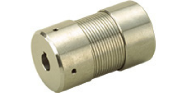
Accurate and easy positioning
The axial and rotational positioning can be done arbitrarily, making it easy to install in equipment that requires precise synchronization adjustment.
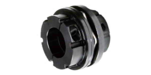
Realization of space saving
Can be designed to be fastened radially to the shaft, enabling space-saving design. This contributes to a compact and lightweight design with low inertia.
High Concentricity
Since the surface pressure is uniform on both the shaft and hub sides, high concentricity is maintained even when the hub outer diameter is reduced. Therefore, unbalance due to centrifugal force can be minimized even when used at high speeds.
Reliable and speedy installation
Secure installation can be done by simply tightening a single bolt to the specified torque. (*Install so that the shaft and hub are in full contact to ensure secure fixation with the appropriate surface pressure against the shaft and hub.)
Ensuring safety in food and medical machinery
The pressure medium uses a highly safe food machinery lubricant (NSF H1 registered), which improves safety in food and medical machinery. (*In case of ETP-E Plus R type)
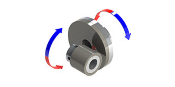
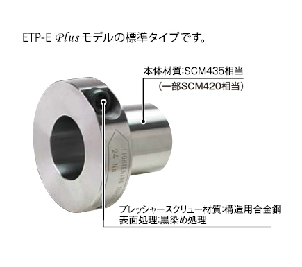
ETP-E Plus Model Construction and Materials
ETP-E Plus (N) Type
ETP-E Plus (C) Type
ETP-E Plus (R) Type
ETP-E Plus (N) Type
| Body Material | SCM435 equivalent |
|---|---|
| Pressure screw material | Structural Alloy Steel |
| Surface Treatment of Pressure Screw | Black Dye Treatment |
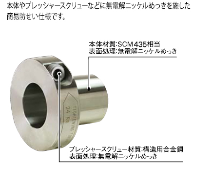
ETP-E Plus (C) Type
| Body Material | SCM435 equivalent |
|---|---|
| Body surface treatment | Electroless nickel plating |
| Pressure Screw Material | Structural Alloy Steel |
| Surface Treatment of Pressure Screw | Electroless Nickel Plating |
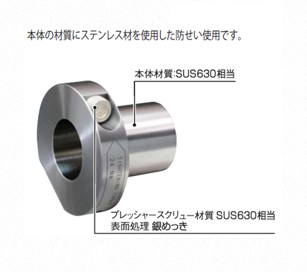
ETP-E Plus (R) Type
| Body Material | Equivalent to SUS630 |
|---|---|
| Pressure screw material | SUS630 or equivalent |
| Surface treatment of pressure screw | Silver plating |
ETP-E Plus Model Design Notes